 Communications
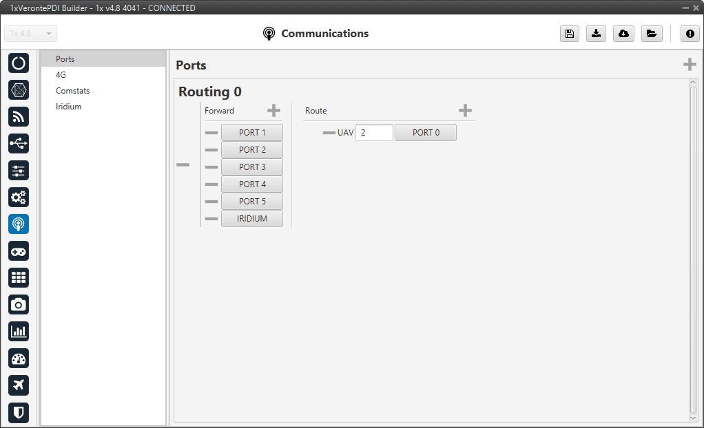
Ports
Ports configuration allows the user to configure which communication ports (Commgr Ports in I/O Setup) will be used for communication. When using the Route feature, Autopilot 1x can be configured to route VCP messages for an external Veronte device with a known address (ID) through a given port.
Ports panel
Each of the different ports can be configured as either of the following options:
Forward: Any messages generated by this unit (i.e. Telemetry or response messages to certain commands) will be sent through these ports.
Route: Any messages received at any Commgr Port with the defined address will be re-sent through the defined port. It is possible to route several addresses through the same port, but is not possible to route the same address through several ports. Only the first configured port will be used. Routing also applies to messages generated by the unit for the defined address.
Note
The same port cannot be used as Forward and Route at the same time.
It is possible to define up to 4 routing setups, which can be switched unsing the Ports action of the Automations menu. Routing 1 will always be selected by default when booting Autopilot 1x.
Application example
A practical example of the use of this menu are 1x ground unit configurations. These configurations should have configured a Routing of Address 2 (Veronte applications, in this case Veronte Ops) through the Commgr port to which the USB consumer is connected (to allow connection to the PC). In this example, Port 0 producer is the one connected to USB consumer.
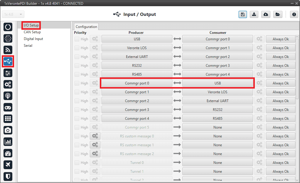
Ports panel - I/O Setup configuration
This way, any messages that are received through a Commgr Port (i.e. through Veronte LOS) with address 2, will be re-routed through Port 0 (USB) and received by Veronte Ops software, including any messages generated by 1x ground unit itself.
Warning
An incorrect Port configuration can disable USB communication. If this happens, 1x will not be able to be detected through Veronte Link software. If this is the case, please visit Forcing maintenance mode - Troubleshooting section of the 1x Hardware Manual.
4G
Checking the Enable box will enable the use of 4G communication through the Veronte LTE Consumer/Producer in the I/O Setup.
Warning
Be careful when configuring 4G communication on the Veronte Autopilot 1x as the configurations for Autopilots 1x with hardware version 4.8 and for Autopilots 1x hardware version 4.5 are not compatible.
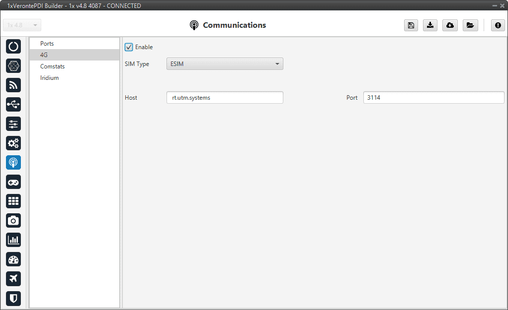
ESIM
The embedded ESIM in Autopilot 1x allows the user to send and receive telemetry using a commercial data provider.
The connection between the air unit and the ground station is established through the Veronte Cloud server. To connect with Veronte Cloud the following parameters have to be set:
Host: rt.utm.systems
Port: 3114
Host and Port can be changed if the used server differs from Veronte Cloud, but the communication protocol does not change.
4G panel - ESIM
Note
In order to use the embedded SIM card, the contract with the data supplier needs to be done through Embention. Please contact sales@embention.com for more information on availability, coverage, suppliers and prices in your country.
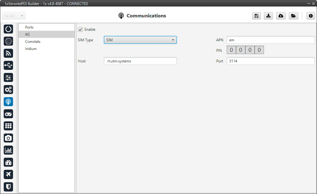
SIM
If needed it is also possible to install a custom SIM card on Autopilot 1x. PIN number and APN (Access Point Name) of the SIM card provider must be defined before enabling the 4G communication
4G panel - SIM
Warning
Introducing the wrong PIN number may block the SIM card.
The installation of the SIM card must be done by Embention during the production of the unit. Please make sure to indicate the interest on using a Custom SIM card when ordering new 1x units.
Comstats
The Comstats feature allows Autopilot 1x to make an estimation of the overall quality of the communication channel.
1x will send periodically (If enabled) a message with its current communication statistics (packets sent and received per second). Then, any other 1x unit can receive this information and compare against its own statistics to estimate the average amount of packets lost in the communication.
The results of this estimation can be monitored in variables RX Packet Error Rate (ID 2000) and TX Packet Error Rate (ID 2001). These variables can be used to enable, for example, failsafe actions in case of degradation or loss of communications.
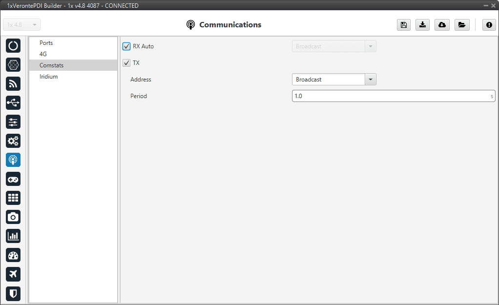
Comstats panel
It is possible to configure the source or destination of the statistics, as well as the frequency at which the Comstats message is sent:
RX Auto: Enabling this option will use the first remote AP found. If this option is disabled, the user must enter manually the address of the unit used for Comstats calculation. For more information on the available addresses, see List of addresses section of the 1x Software Manual.
TX: When enabled, the unit will periodically send its Comstats message (set the period). Enter the address to which the message should be sent. For more information on the available addresses, see List of addresses section of the 1x Software Manual.
Note
Enabling TX will enable Autopilot 1x to send its Comstats message, but in order to compute Packet Error rate it’s necessary to receive the TX message from a different unit.
Warning
Packet error rate is a good indicator of the status of the communication, but it is not representative of the radiolink status. For monitoring the status of the radiolink RSSI Variables (820-822) shall be used instead. Depending on the configuration it is posible to have bad Error rates with good RSSI (overloaded radiolink) or good Error rates with bad RSSI (degraded communication with low load on radiolink). For the best results, it is recommended to use a combination of both statistics for failsafe automations.
Iridium
Checking the Enable box will enable the use of Iridium communication through the Iridium Consumer/Producer in the I/O Setup.
Warning
Before using the module, the user will have to register both of them (sender/receiver) in the RockBlock website. For further information about the registration process, visit the RockBlock Management System.
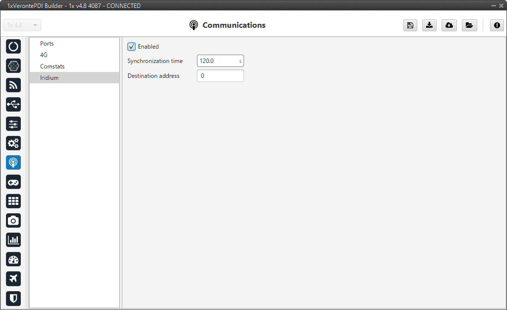
Iridium panel
In this menu the following parameters have to be set:
Synchronization time: This is the transmission period, i.e., the time between 2 consecutive messages. This is a parameter that the user should configure taking into consideration its mission.
Destination address: SN (Serial Number) of the destination Iridium module.
Note
To configure the syncronization time, it would be advisable to think about how the user want to use the Iridium communication. The user will pay for credits, and each credit means one message. Each individual message has to be paid, so the syncronization time can be configured in order not to run out of credits.